Calculating geometric properties with the Fault Seal strip
With the Geometric Properties tool (Model> Fault Seal > Geometric Properties) you can calculate fault displacement properties for your 3D grid faults, i.e. fault throw, fault heave, fault dip displacement and true displacement. For true displacement you need to enter the strike displacement for the respective fault(s) on the form.
The tool has two main purposes:
- To QC fault displacement, which can be important in structurally complex fields.
- To create the required 'calculation points' and geometric properties for the Fault Seal Modeling workflow, see Requirements and input for Fault Seal Modeling.
In order to use the tool, you need to have fault cutoff lines available under your 3D Structural Model > Fault Cutoff Lines item in the JewelExplorer. If you don't have fault cutoff lines, calculate them first with the Fault Cutoff Lines form of the Structural Modeling workflow.
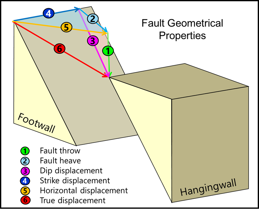
Schematic diagram of an oblique fault with the components fault throw (vertical component), fault heave (stratigraphic apparent horizontal component) and dip displacement (dip-parallel slip component) indicated with the numbers 1, 2 and 3. click to enlarge
How the displacement property is calculated
The algorithm takes an upper footwall cutoff line and the corresponding hanging wall cutoff line and calculates the offset. The same is done for the lower pair of cutoff lines, after which smart interpolation (supporting for example growth faults) between both end-points takes place. The values are projected on a point set, which has a node at each centerpoint of the common area of neighboring cells on opposite sides of the fault (called calculation points in the Fault Seal Modeling workflow). Note that a point set node is generated for each common area of any two cells which are in touch across a fault, irrespective of I,J,K indices.
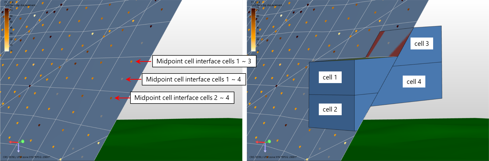
The point set has a node at each midpoint of the interface of any two cells on opposite sides of the fault. All cells are taken into account, including 'multiple IJK' cells. Each node receives a geometric property value which can be visualized as a property of the point set in the 3D View. click to enlarge
To calculate the fault geometry properties
Before you start, make sure you have fault cutoff lines available under your structural model in the JewelExplorer (a requirement for the calculation of fault geometry properties).
- On the Geometric Properties form, select a 3D Grid in the Model drop-down list.
- Select one or more faults in the Fault column at the left side of the table for which you want to calculate the fault geometry properties (all faults in the selected structural model are listed).
- (Only for true displacement) In the column Strike Displacement, enter the strike (horizontal displacement) of your fault(s). The strike displacement is the strike-slip component of the fault displacement, nr. 4 in the schematic diagram above. Strike displacement is only used for calculation of 'true displacement'; in all other fault displacement calculations (throw, heave and dip displacement) the strike slip component plays no role. If you calculate the true displacement property but leave 'strike displacement' empty in the table, the true displacement is calculated with 0 strike.
- Under Properties at the right side of the form, select the fault geometry properties that you want to calculate. See the schematic diagram above for a graphical explanation of each of these properties.
-
You can choose to check the option 'Also create tri-meshes' which allows you to generate tri-meshes next to the point sets at every step of the fault seal analysis. These tri-meshes show the (interpolated) properties for QC and visualization purposes, as their continuous nature can make the interpretation easier compared to point sets. However, the point set representation remains the most direct representation of the calculations that are carried out.
- Click Apply (and keep the form open) or OK to calculate the properties.
- Upon calculation, a point set with the calculated geometric properties (plus property 'Connection area' which is required for the Fault Seal Modeling workflow) is generated per selected fault and stored in an auto-generated Surface Set which carries the name of the associated 3D Grid. If you selected 'Also create tri-meshes', these are also available in the created surface set. To QC the fault displacement, visualize the fault(s) in the 3D View in combination with the point set and the geometric property (see example below).
 and in the section 'Display parameters', select either Foot Wall or Hanging Wall under 'Display mode'. Here, you can also select Both, which can be used to visualize both the hanging and footwall side of the fault simultaneously, and can be used (when selecting a suitable property) for visualization of juxtaposition.
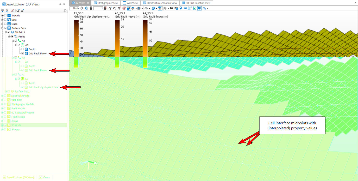
Example of calculated fault geometry properties. The properties are stored as properties of a point set, generated for each fault for which a geometric property calculation is performed. In the JewelExplorer, the point sets are stored in an auto-generated Surface Set, which carries the name of the associated 3D Grid. In the 3D View, these properties can be visualized on the nodes of each point set against the associated grid fault. If you choose the option 'Also create tri-meshes', the form also produces tri-meshes with properties in the same surface set for QC and visualization. click to enlarge